3D Projects
3D stuff: CNC, 3D printing, 3D modeling, etc.
When the weather isn't nice enough to work on my car, and I'm not feeling inspired to weld, I work 3D projects.
LANDSCAPE OF AN OYSTER
2020-05-16 11:09:22
by: jovial_cynic
by: jovial_cynic
I'm not sure what I enjoy more, taking digital creations and bringing them into the physical world by building or printing them...or taking real-world things and bringing them into the digital world.
This was one of my first successful 3D scans, using photogrammetry. The video I posted explains it pretty well.
Here are a couple of photos of the shell I used for the scan:
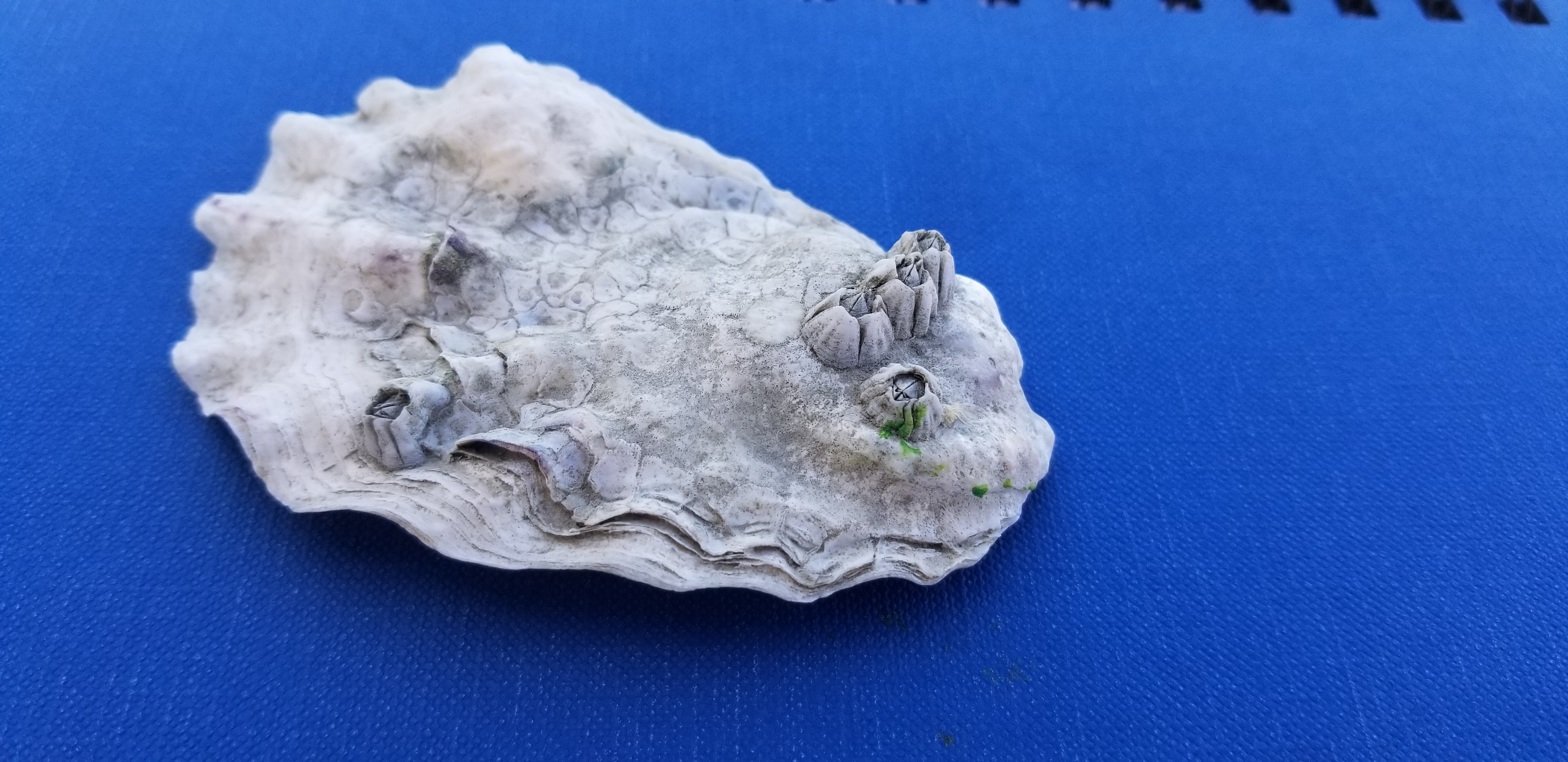
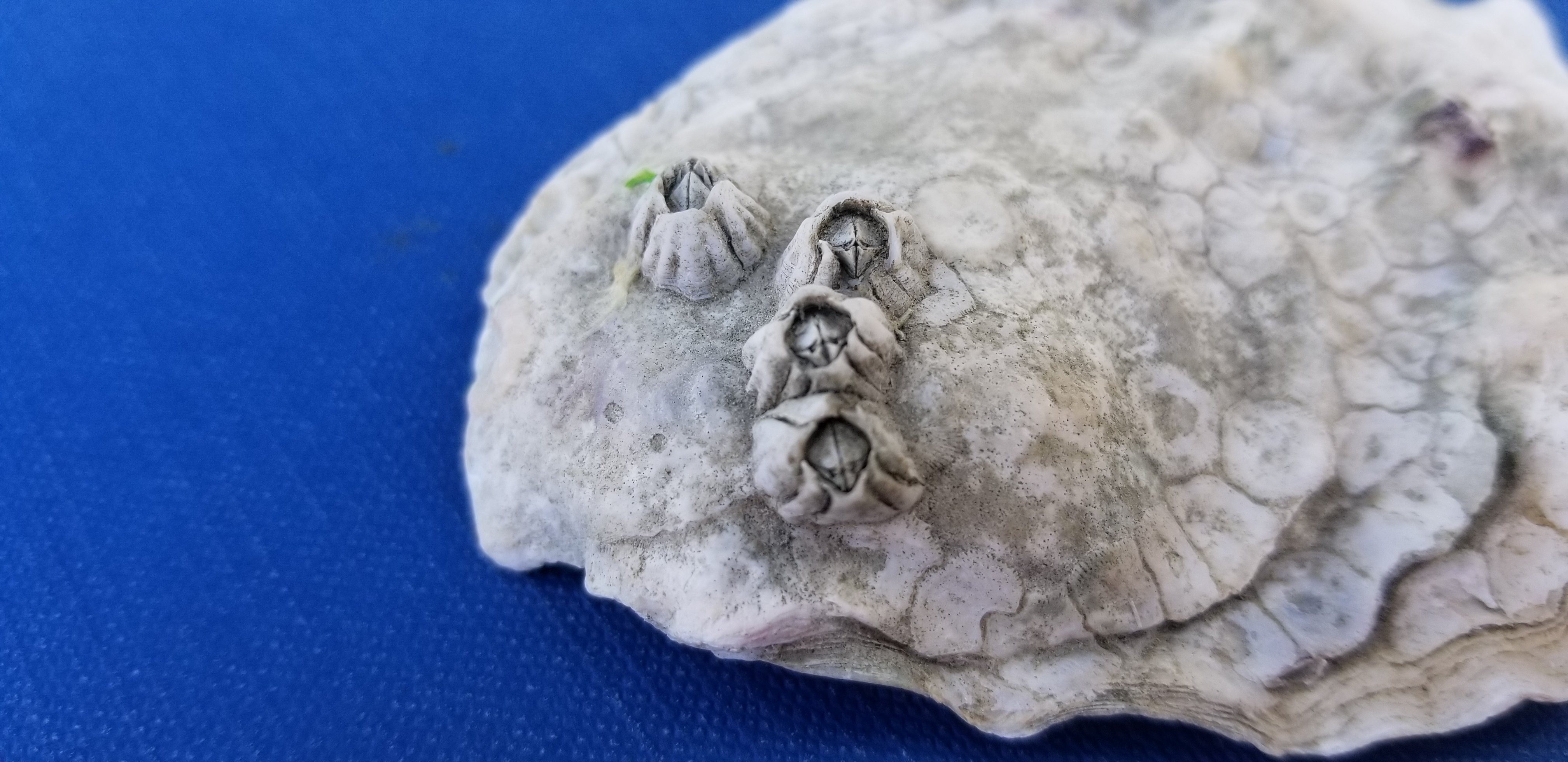
If you'd like to recreate the model, here's the link to the photo set that you can download and run through your own photogrammetry program.
comments [0]
3D SCANNER PROJECT - PART 3
2020-04-28 09:07:29
by: jovial_cynic
by: jovial_cynic
With the physical build of the scanning platform, and the Arduino and C++ code figured out, the next step was to try to actually scan something. You can see in the video above that the scanning table rotates, and the VL6180 range-finding chip moves up. It may not be obvious from the video, but the chip only moves up after each complete revolution of the platform.
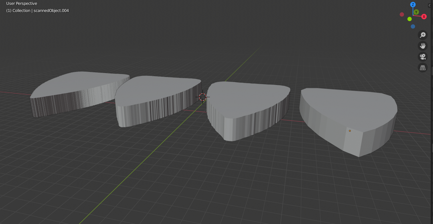
Before really scanning up the object, I wanted to get a sense of the differences in resolution. From left to right, you can see how the walls of the object go from being fairly fine to much more course. In each case, the overall shape is precisely what I'm going for.
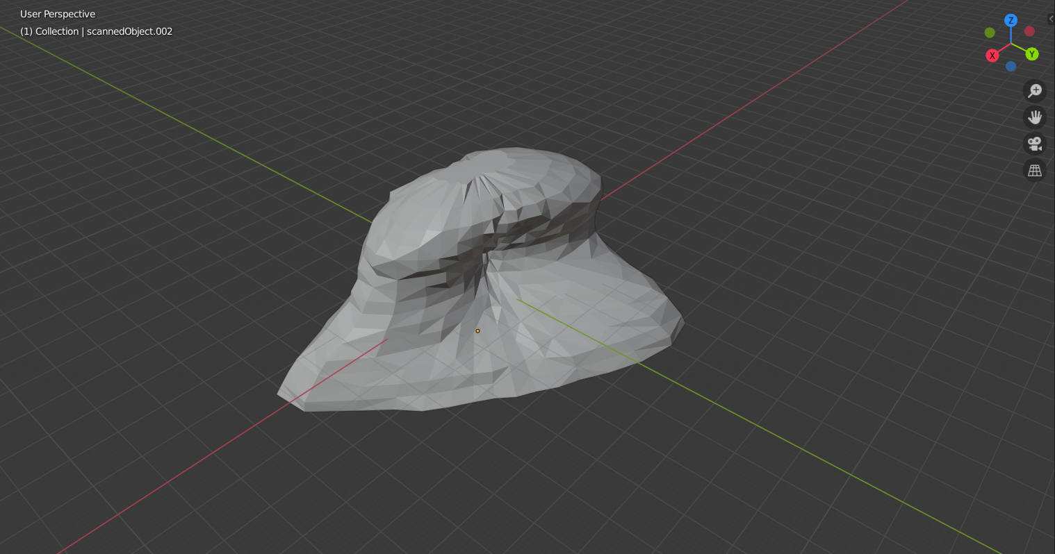
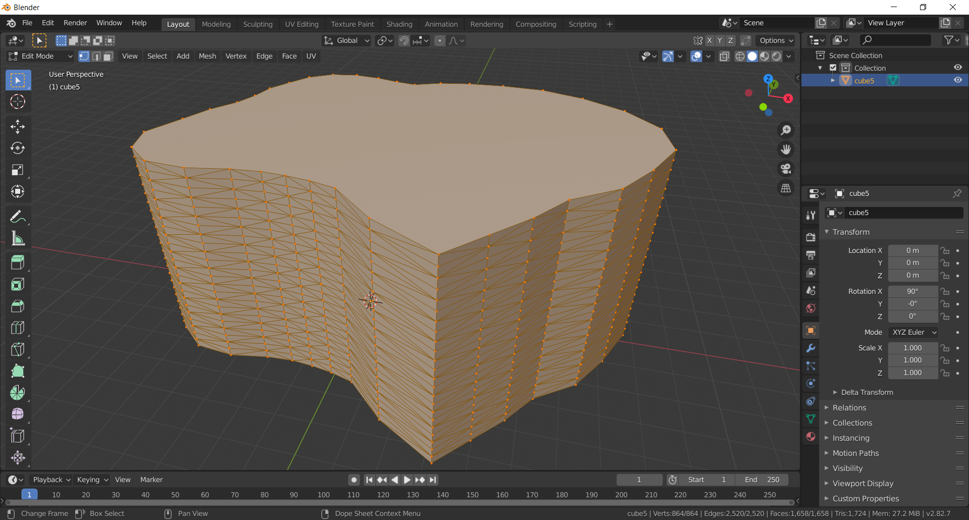
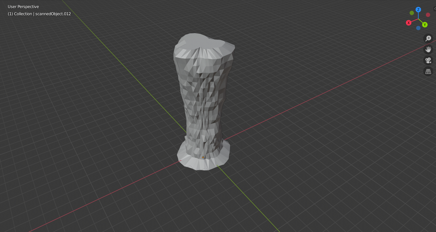
Well would you look at that! It's not a perfect scan, but it definitely resembles the object! You can see all the triangles that were created for the .OBJ file. Those were created using tesselation.
In order to tesselate the scanned object, I had to pick a polygon that I felt would be simple yet detailed enough to handle curves in the object. Triangles make sense to me, so the uprights faces of the object are just a bunch of alternating right-angle triangles.
The basic format is:
[===== ROW 2 =======]
|---||---//||---|
|...||..//.||...|
|...||.//..||...|
|---||//...||---|
[===== ROW 1 =======]
Here, you can see how the object is being built, piece by piece. The first step is to lay down the bottom face, and then the code builds up by placing alternating vertical triangles. This particular example is 2-unit height rectangular box.
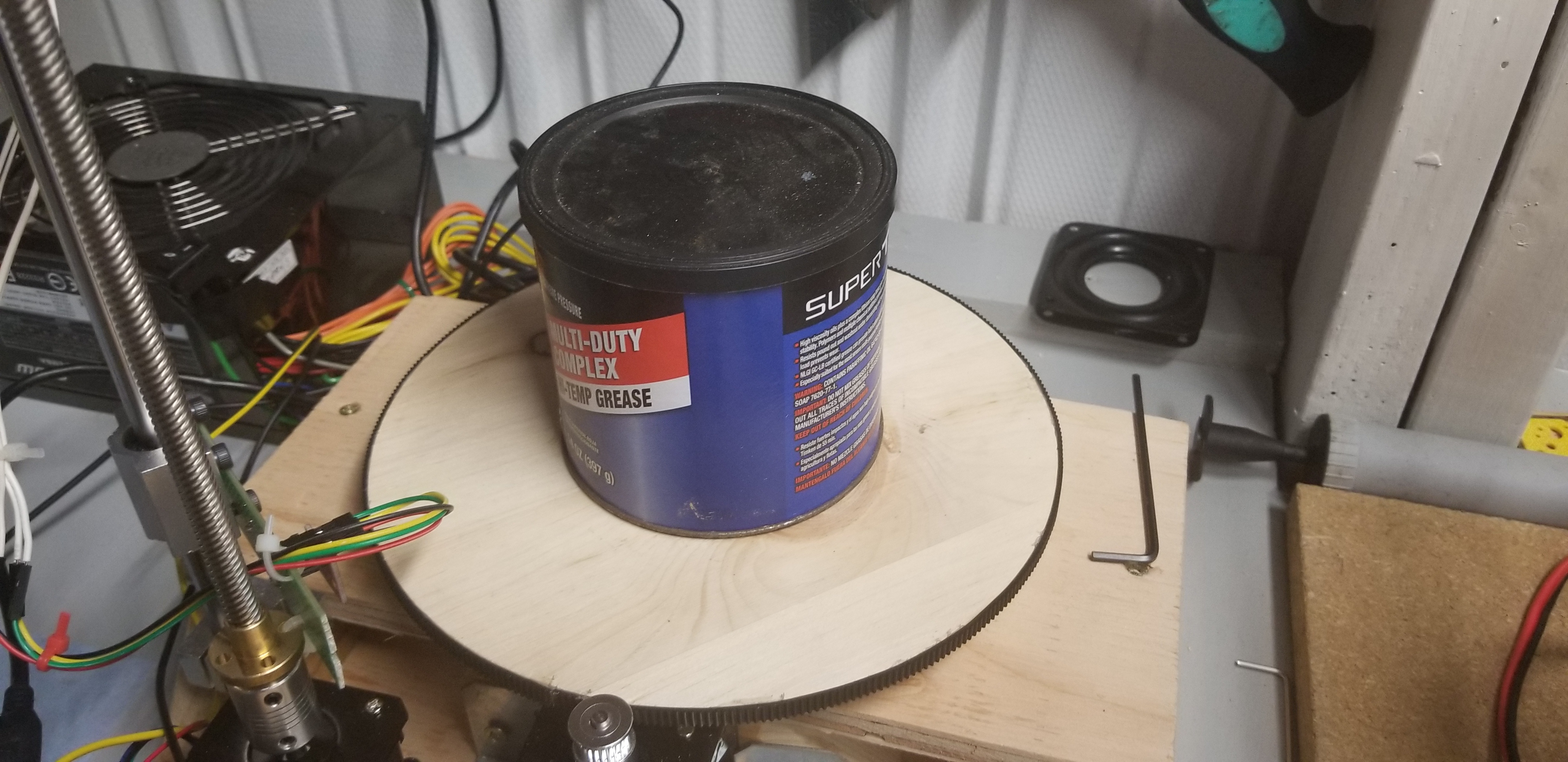
The next object to scan was a simple can. Well, I thought it would be simple, but as it turned out, this can of grease became the starting point of my discovery that the VL6180 might not be the best range finder for this project.
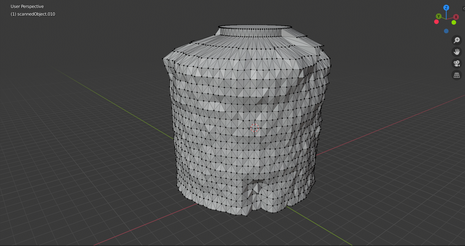
Here's the full scan, and you can see that it's... lumpy. It makes sense - we're dealing with 1mm units, and the machine has an accuracy of 1mm, so every single point of distance can be off by a pretty noticeable amount.

In order to make sure that this wasn't a one-off error, I scanned the can a few more times and got similar results. Even with varying degrees of resolution, there were areas that were consistently problematic.

In particular, take a look at that little notch that appeared at the bottom of the scan. It's on all of them!
As it turned out, the "notch" happened repeatedly because there is a small black square on the can itself, and the color of the square actually throws off the distance-reading! This would literally mean that if I had alternating black and white strips on the object I'm scanning, I would have that alternating variation in scan distance. That's terrible!

I tried the scan again with a uniform-colored object. I figured this candle would do a better job giving me a smooth cylindrical shape...
... but it turns out that translucent objects cause even more difficulty for the scanner, because the laser is able to penetrate the outer layer of the object, giving a very bad reading back to the scanner. This is quite comical, really.
I think the next step may be to get some kind of spray coating to provide a uniform, non-translucent surface for the scanner. But that's a future project. In the meanwhile, using photogrammetry may still be a good alternative.
Well, that includes this 3-part 3D scanning project documentation. This was a fun project, and I learned a ton about stepper motor controls, .OBJ file generation, and range-finding chips.
If you missed the previous entries, here you go:
Part 1
Part 2
comments [0]
3D SCANNER PROJECT - PART 2
2020-04-25 21:09:26
by: jovial_cynic
by: jovial_cynic
In the previous post for this project, I explained the process by which I converted data points for a rectangle on a polar grid into a cartesian grid.
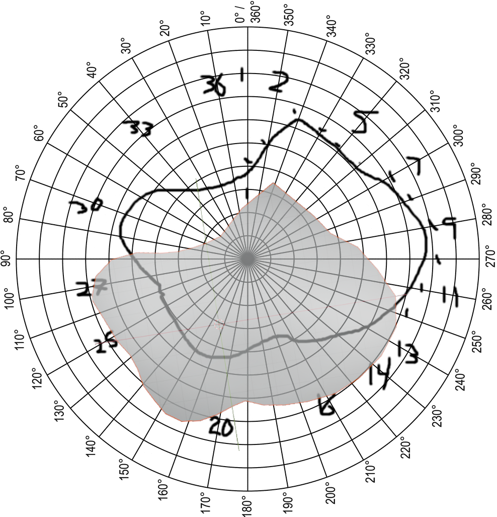
The next step was to create a more complex shape. So I just drew something random onto the polar grid.
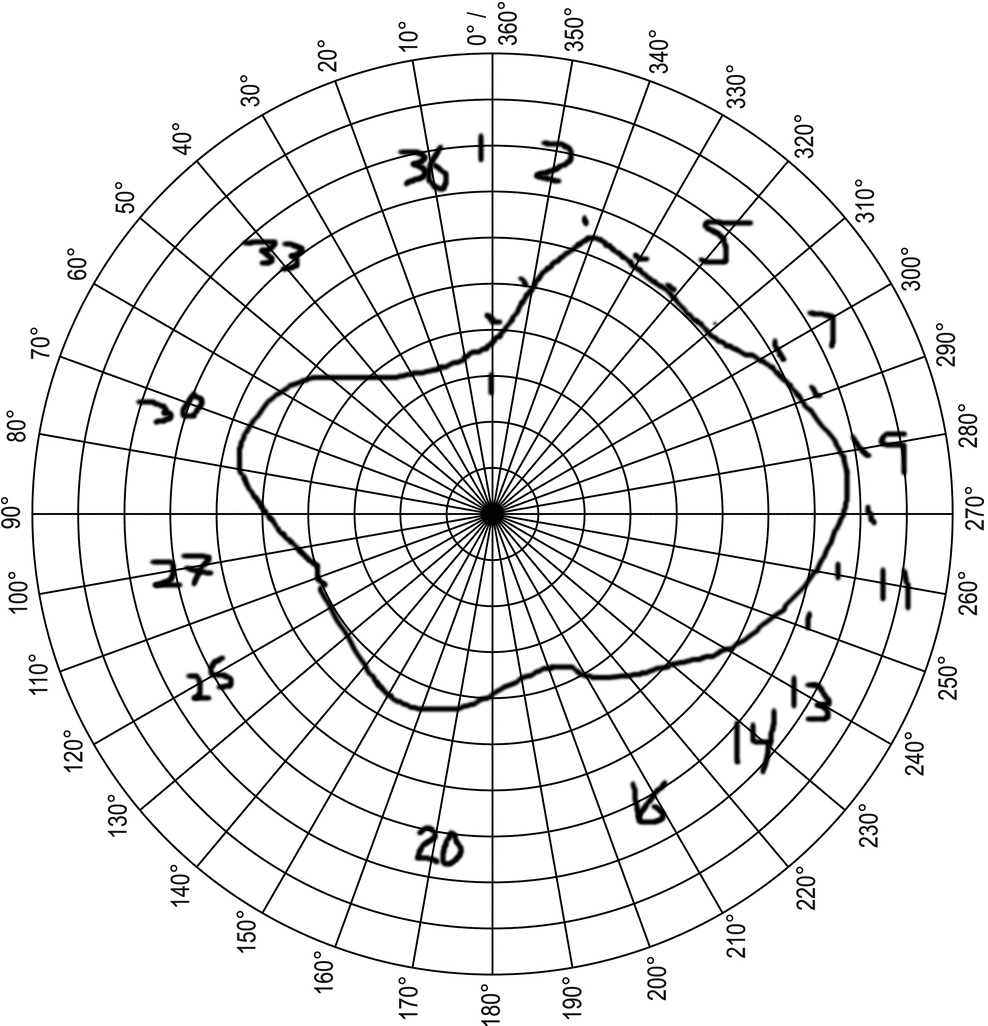
Here's the drawing. For clarification, the numbers on the grid are just something I used to count polar lines, because I had a difficult time keeping track of them. Also, I apparently counted them... backwards? Fortunately, for this demonstration, it doesn't really matter. But if you want to recreate this project, you probably want to do it in the correct order.
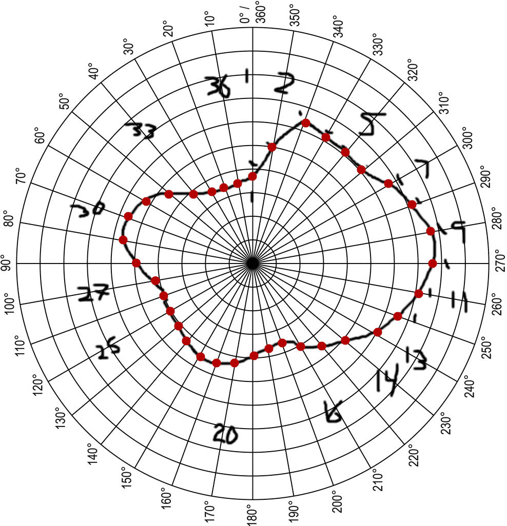
Here, I highlighted the points on each polar line. Like I said on the last post, the scanner measures from the outer edge of the scanner to the object, but the data we need is the distance from the edge of the object to the center of the platform. So, you just subtract the scan distance from the total distance (center-to-scanner), and you're good to go.
The next step is to take the polar grid data, run it through the SIN/COS formulas to generate the X, Y coordinates, and then convert those X, Y coordinates into a .OBJ file.
The structure of a basic .OBJ file (without materials) is pretty straight forward:
V [coordinate X] [coordinate Z] [coordinate Y]
V [coordinate X] [coordinate Z] [coordinate Y]
V [coordinate X] [coordinate Z] [coordinate Y]
V [coordinate X] [coordinate Z] [coordinate Y]
F 1 2 3 4
Each line with a "V" is the X, Z, and Y coordinates. Note that the Z is in the center. It's kind of weird. But that's what it is.
The line with an "F" is a flat plane of connected points, with the numbers representing the "V" lines above. As there's only four "V" lines, "F 1 2 3 4" connects points 1, 2, 3, and 4 in that order.
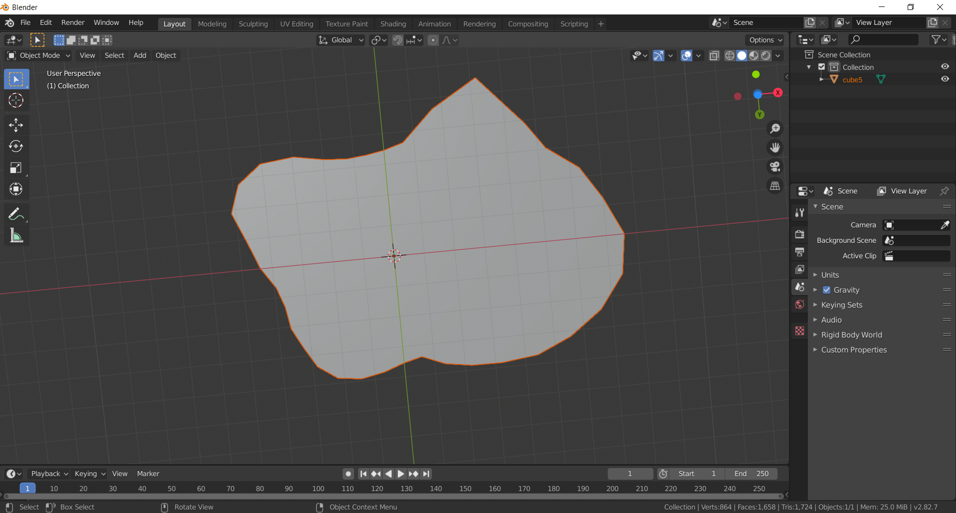
Here's the generated .OBJ file, viewed in Blender. It's just a flat plane, since the Z coordinate was just 0.
Here's the .OBJ file next to the original drawing.
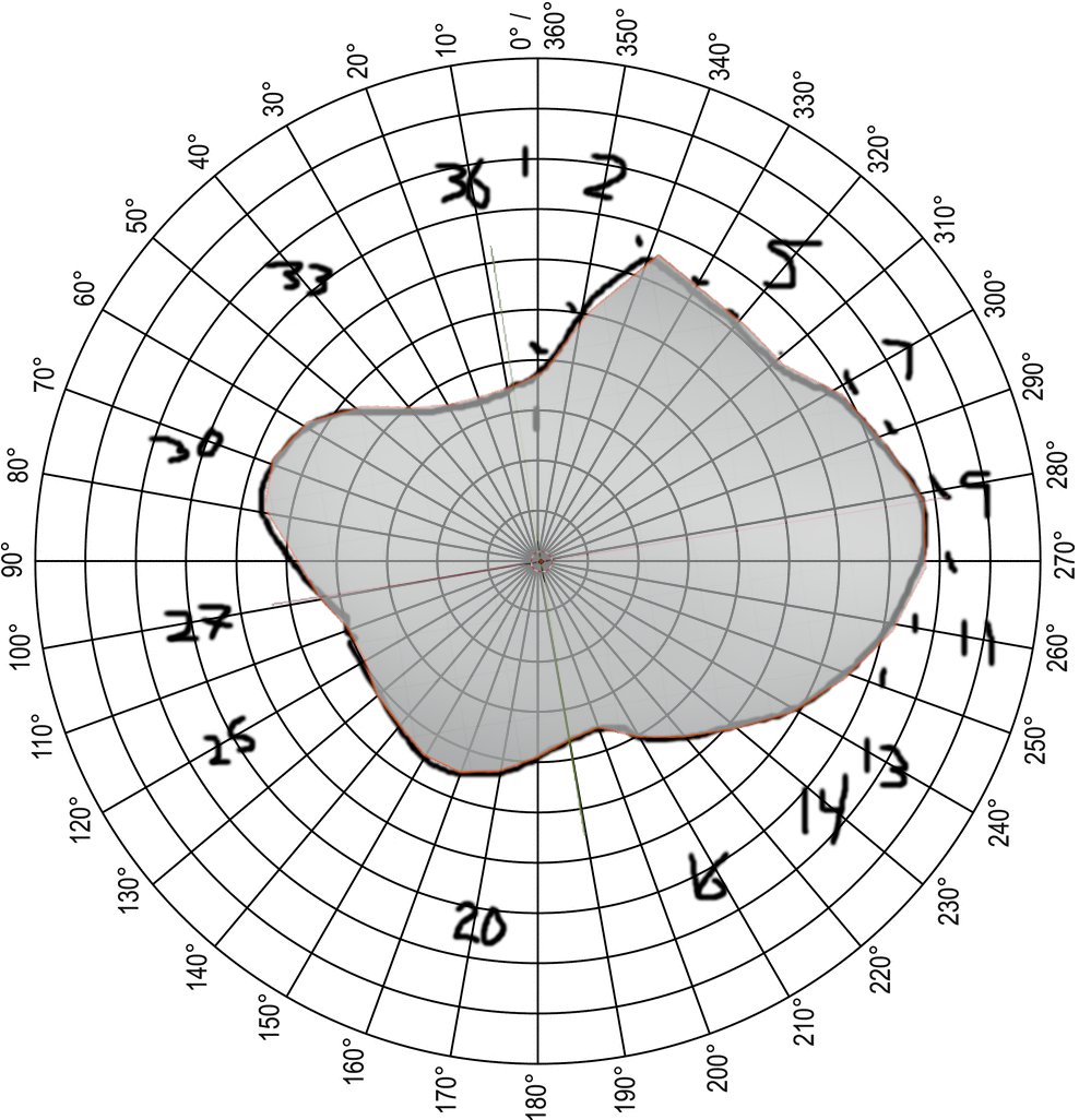
Perfect fit!
In addition to creating a flat plane, I wrote some code that turns the flat plane into a 3D object. I'll explain more in Part 3, but the basic idea is that as the object increases in height, each vertical point becomes one of the points of a triangle on the exterior surface.
This particular object wasn't scanned in - it was basically just extruded along the Z axis, so the walls of the object are uniform in their vertical dimension. Each "layer" is identical. On real objects that are scanned in, each layer would be a little different, and the triangles are good at representing those differences.
Part 1
Part 3
comments [0]
3D SCANNER PROJECT - PART 1
2020-04-24 18:49:37
by: jovial_cynic
by: jovial_cynic

Last year around this time, I spent a bunch of time building my own 3D Scanner, being inspired by Alex from Super Make Something. It wasn't quite the success I hoped it would be, but I figured I'd share the work I did, and maybe this will inspire you to build and improve on it.
The Build
The first part of this project was to build the scanning table. The SuperMakeSomething video shows a 3D printed table assembly, but I wanted something bigger and sturdier, so I decided to build my own.
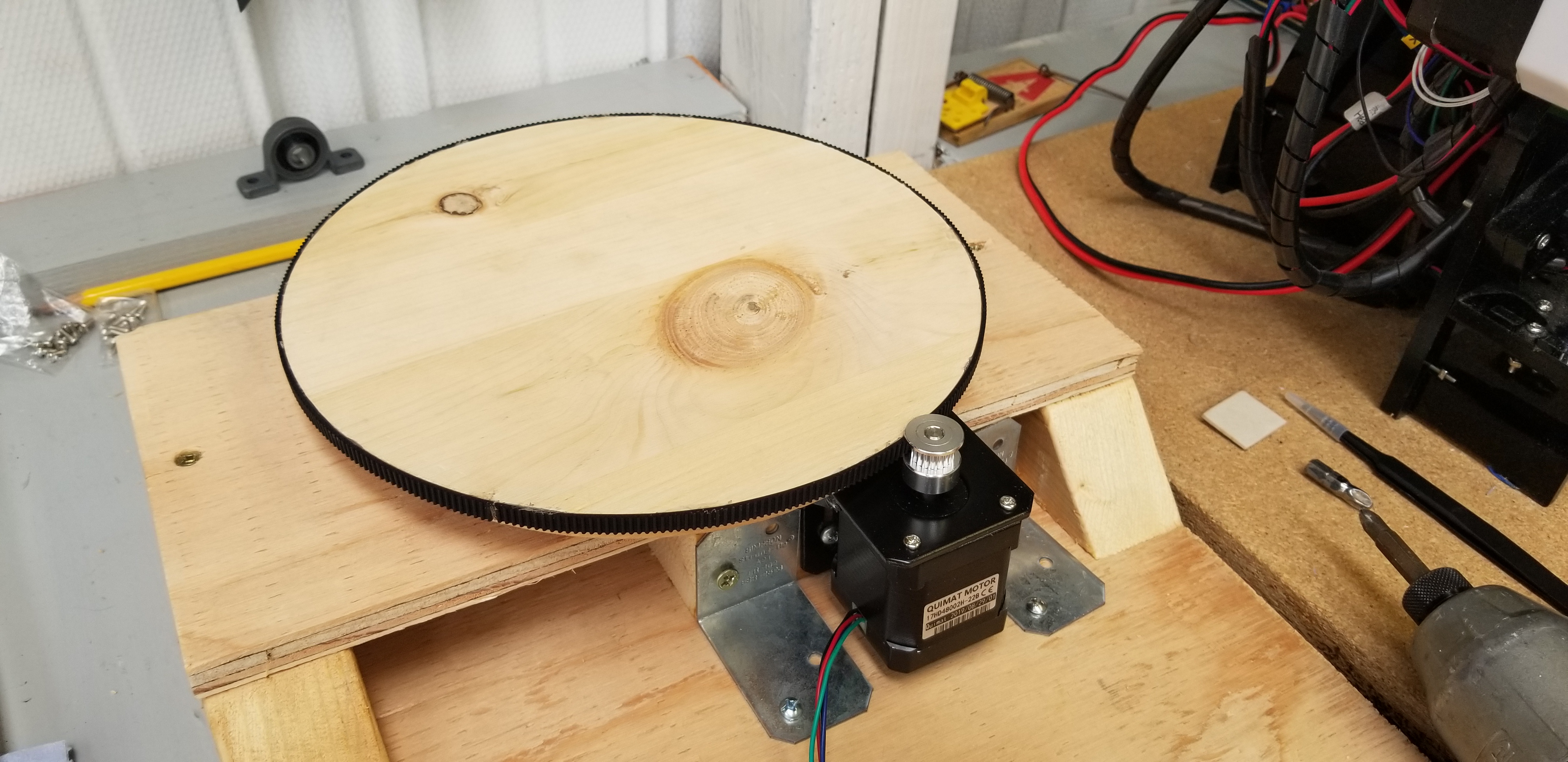
The first thing was to get a platform big enough and to wrap it in a track band so my stepper motors could spin it.

I thought about mounting the platform directly to the stepper motor, but the belt-driven option allows some additional gearing in case I wanted to increase the scan resolution.
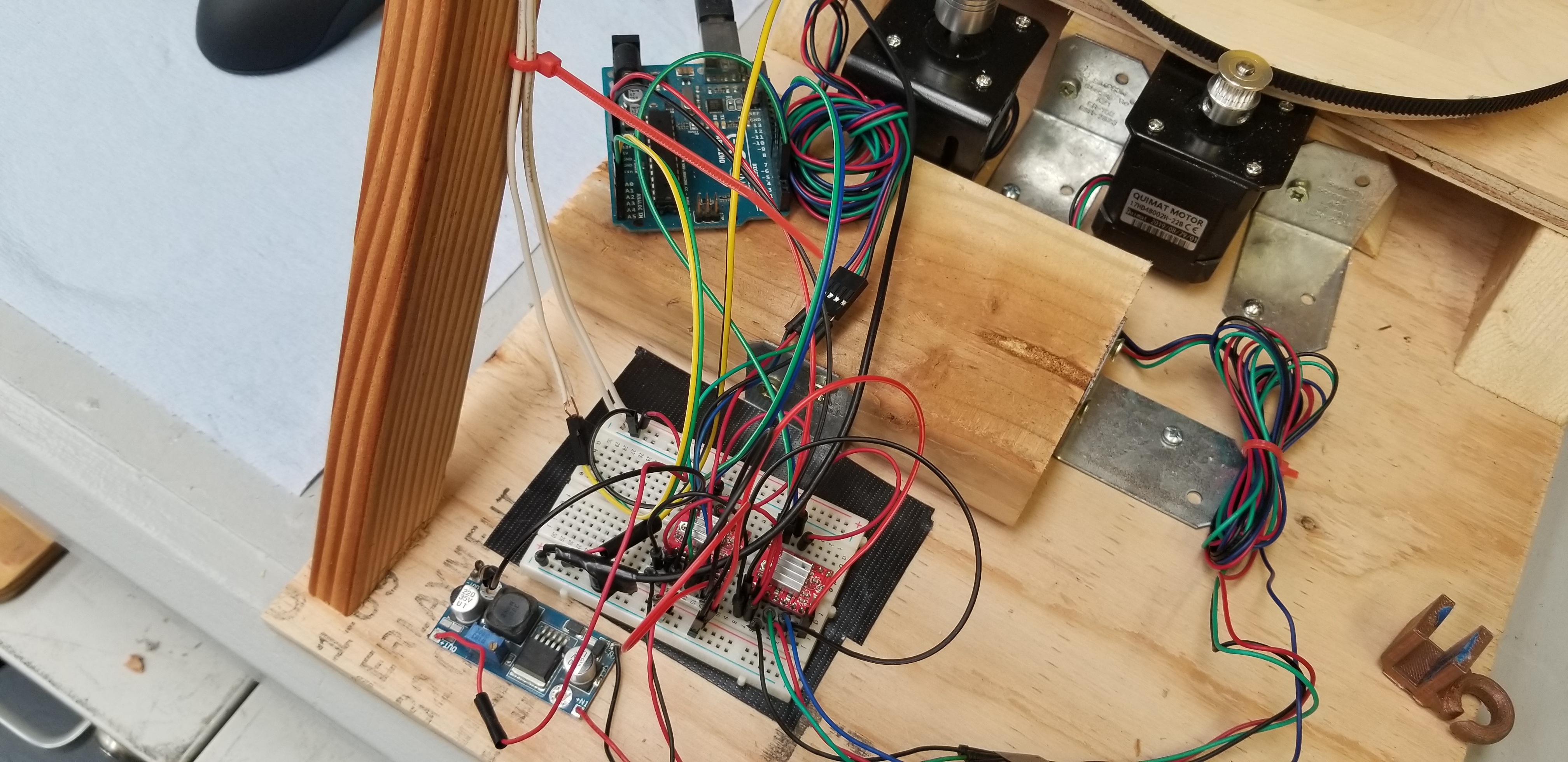
Once the platform was done, the next thing was to get the motor assemblies put together, the VL6180 Time of Flight chip wired in, and the stepper motor controllers connected.
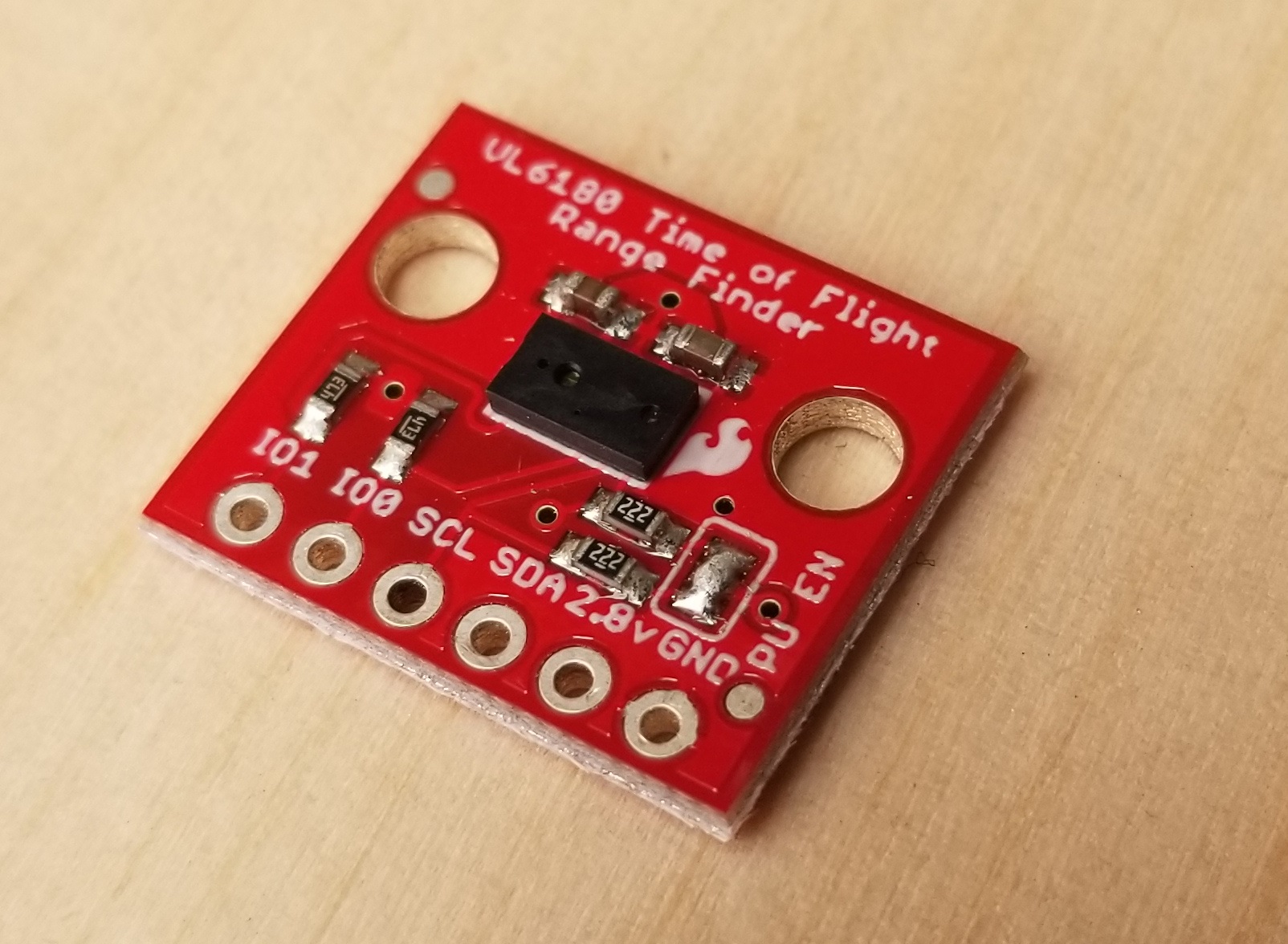
The VL6180 is a high-resolution proximity sensor. At 1mm resolution, it seemed like a really interesting way to build a pretty accurate scanner. I could set the scanner to take a reading of an object on the platform as it spun, and after each full pass, move the scanner up and scan again.
The Code
The coding for this project was really two parts: the Arduino (to control the stepper motors, and to trigger the VL6180), and the C++ code I used to convert the captured distance data into a 3D model.
The Arduino portion was fairly simple. With the table moving 360 degrees, the first part of the code was some simple stepper-motor control. Depending on how I wanted the resolution, I could either set the code to measure the distance every degree (360 scans per pass), or I could go every 5 degrees (72 scans per pass), or I could go much rougher and go every 36 degrees (10 scans per pass).
Once the platform makes a full pass, the next part of the code instructs the stepper motor to move the VL6180 up. Similarly to the platform resolution, the greater the height increase, the lower the vertical resolution.
In order to save the scan data, the code was set up to send the reading out to the serial monitor where it could be copied and pasted into a text file. Easy peasy.
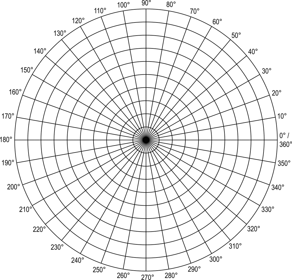
The next part required a bit of math. The scans provide the data in a polar grid. It means that each scan is the distance between the scanner and the edge of the object, at a particular degree. If we know the distance from the scanner to the center of the scan table, we can subtract the scanner-to-edge distance from the scanner-to-center distance.
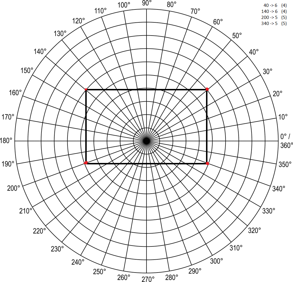
Let's take this rectangle, for example. Because it's not a complex shape, I'm going to act like we're just scanning the four points. In order to visualize this properly, you have to imagine that the VL6180 is stationary, at the right-side of the image (at the 0/360-degree mark). Then you have to visualize the grid rotating clock-wise, so that eventually, the 40-degree line meets up with the VL6180. If the chip takes a data reading only at the 4 points marked in red, you end up with the following:
-At 40 degrees, the scanner reads a distance of 4, which means that it is 6 units from the center
- At 140 degrees; 6 units from the center
- At 200 degrees, 5 units from the center
- At 340 degrees, 5 units from the center
The next step is to convert these polar-grid data points into X,Y coordinates. Here's the formula for each:
X = SIN(DEGREES * 3.1415/180) * DISTANCE FROM CENTER
Y = COS(DEGREES * 3.1415/180) * DISTANCE FROM CENTER
Obviously, I'm just using a rough approximation for PI, but it's good enough for this. When you run each of the 4 polar-grid data points through the formulas, you get the following:
1: 3.86, 4.60
2: 3.86, -4.60
3: -1.71, -4.70
4: -1.71, 4.70

Perfect! Here's the link for Part 2 and Part 3 of this project.
comments [0]
MAJOR UPDATES ON THE CNC MACHINE
2013-06-30 09:34:07
by: jovial_cynic
by: jovial_cynic
I currently have a fully operational 4x4' CNC machine!
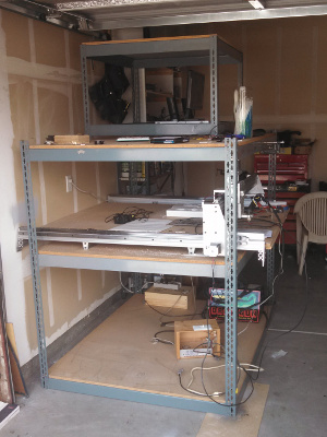
Here it is fully assembled in the garage.

It's using the G540 motor controller, connected to NEMA23 motors.
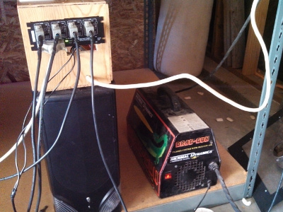
Here are the motor control wires, cobbled together to make sure it works.
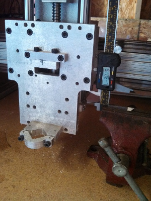
Calibrating the machine with an electronic gauge.
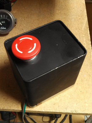
Every CNC machine needs a panic button. Here is mine.
comments [0]
Here it is fully assembled in the garage.
It's using the G540 motor controller, connected to NEMA23 motors.
Here are the motor control wires, cobbled together to make sure it works.
Calibrating the machine with an electronic gauge.
Every CNC machine needs a panic button. Here is mine.
comments [0]
2008-03-08: Y-AXIS NOW OPERATIONAL 2008-03-02: FIRST RUN: X-AXIS 2008-01-10: POWER SUPPLY WIRED UP 2007-12-17: CNC POWER SUPPLY 2007-11-26: ACTUATORS 2007-06-29: INSTRUCTABLES 2007-06-12: CNC: BUYING PARTS AT HOME DEPOT #1 2007-06-08: SCAVENGING PARTS 2007-06-02: STEPPER MOTORS 2007-06-01: CNC CONTROLLER 2007-06-01: DIY CNC MACHINE

