3D SCANNER PROJECT - PART 2
April 25, 2020
by: jovial_cynic
by: jovial_cynic
In the previous post for this project, I explained the process by which I converted data points for a rectangle on a polar grid into a cartesian grid.
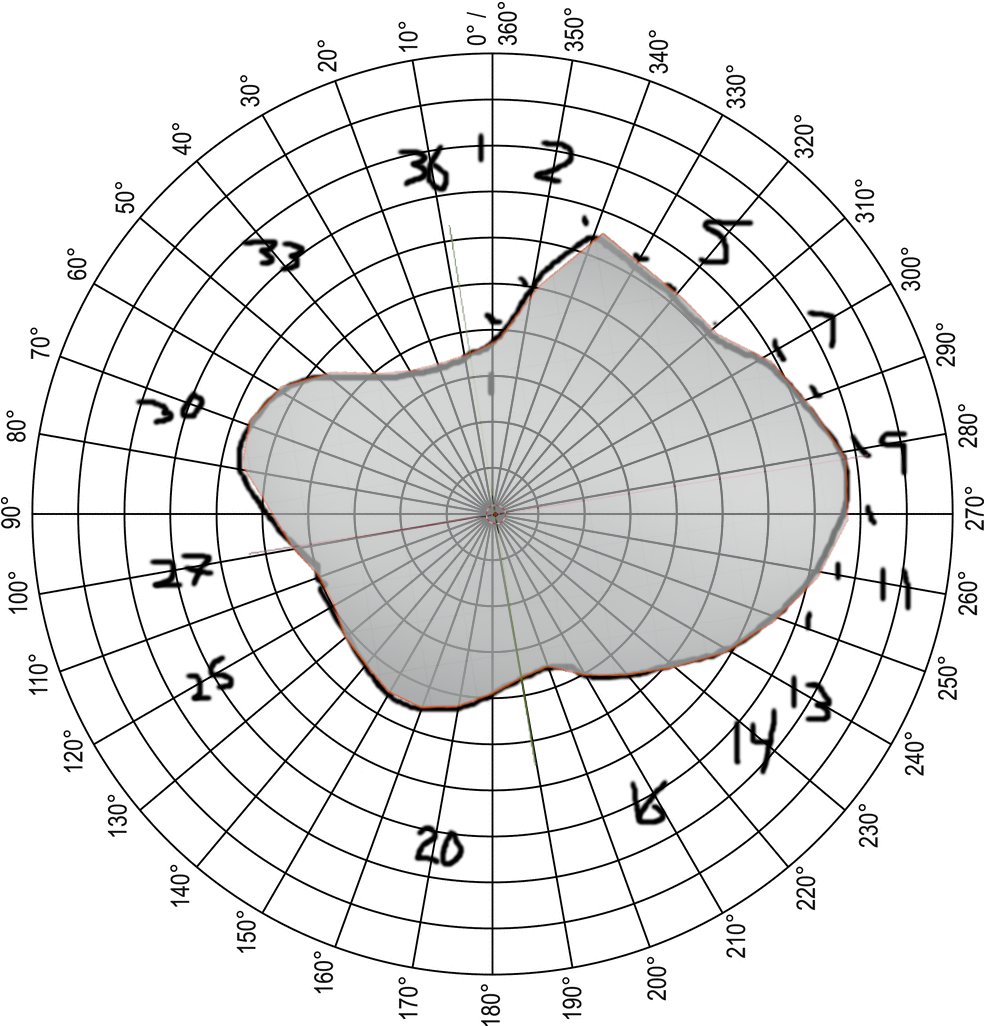
The next step was to create a more complex shape. So I just drew something random onto the polar grid.
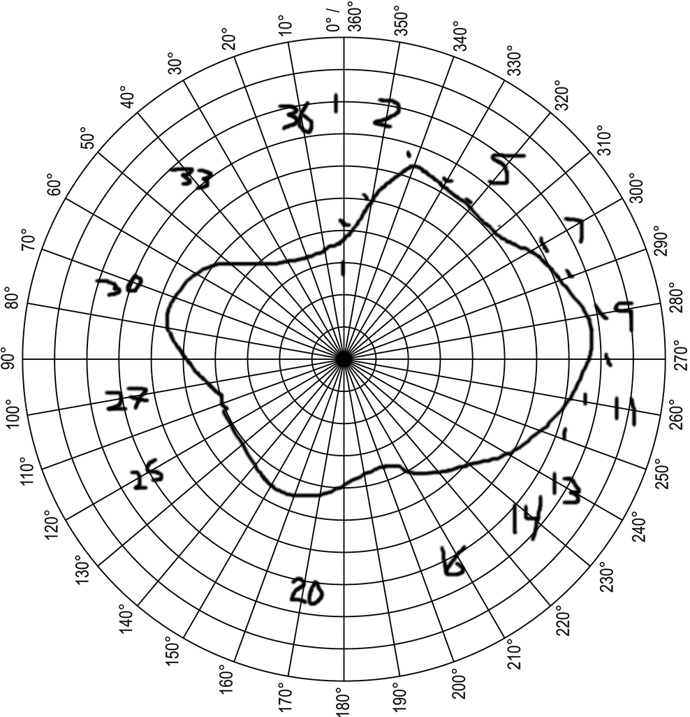
Here's the drawing. For clarification, the numbers on the grid are just something I used to count polar lines, because I had a difficult time keeping track of them. Also, I apparently counted them... backwards? Fortunately, for this demonstration, it doesn't really matter. But if you want to recreate this project, you probably want to do it in the correct order.
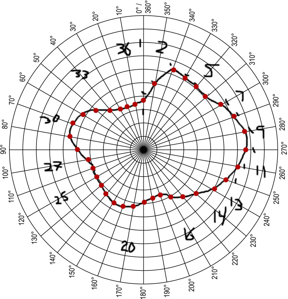
Here, I highlighted the points on each polar line. Like I said on the last post, the scanner measures from the outer edge of the scanner to the object, but the data we need is the distance from the edge of the object to the center of the platform. So, you just subtract the scan distance from the total distance (center-to-scanner), and you're good to go.
The next step is to take the polar grid data, run it through the SIN/COS formulas to generate the X, Y coordinates, and then convert those X, Y coordinates into a .OBJ file.
The structure of a basic .OBJ file (without materials) is pretty straight forward:
V [coordinate X] [coordinate Z] [coordinate Y]
V [coordinate X] [coordinate Z] [coordinate Y]
V [coordinate X] [coordinate Z] [coordinate Y]
V [coordinate X] [coordinate Z] [coordinate Y]
F 1 2 3 4
Each line with a "V" is the X, Z, and Y coordinates. Note that the Z is in the center. It's kind of weird. But that's what it is.
The line with an "F" is a flat plane of connected points, with the numbers representing the "V" lines above. As there's only four "V" lines, "F 1 2 3 4" connects points 1, 2, 3, and 4 in that order.
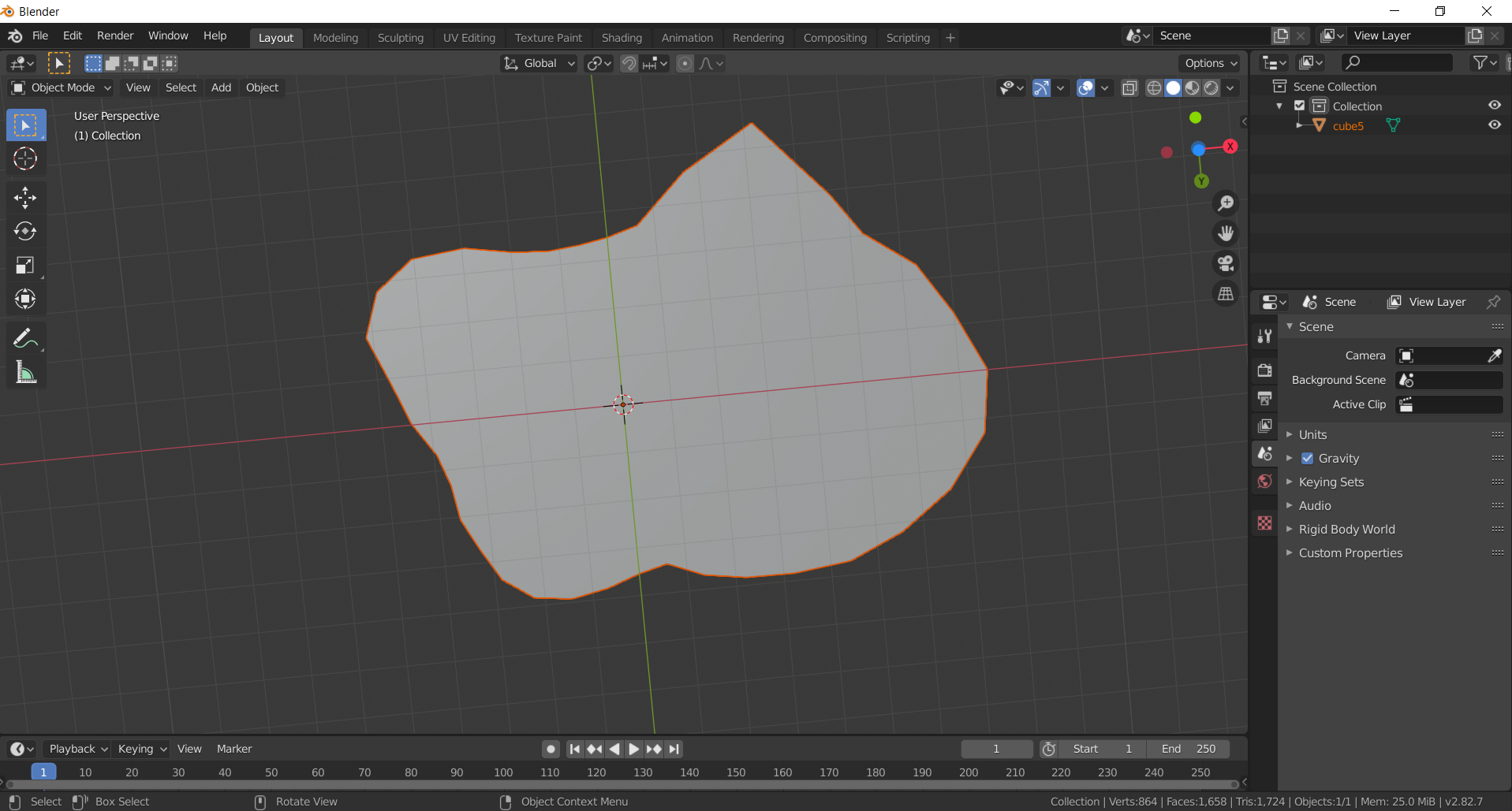
Here's the generated .OBJ file, viewed in Blender. It's just a flat plane, since the Z coordinate was just 0.
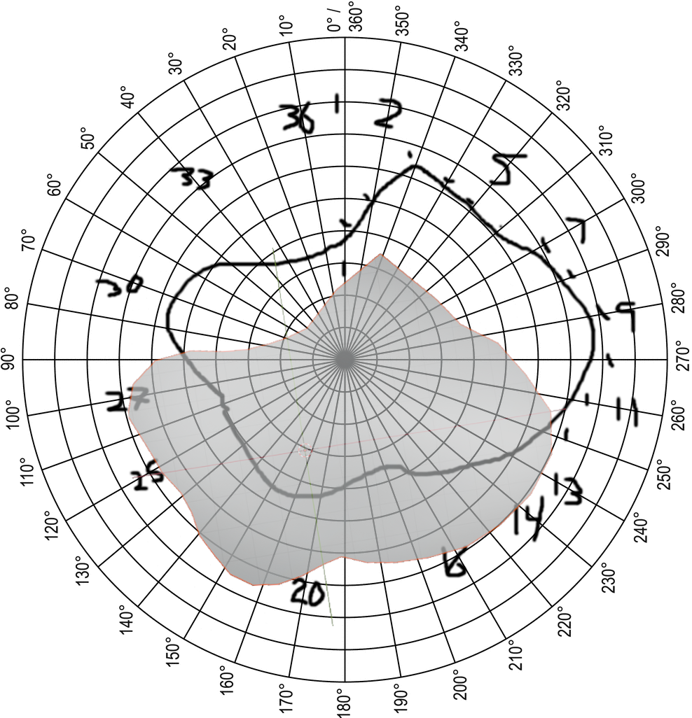
Here's the .OBJ file next to the original drawing.
Perfect fit!
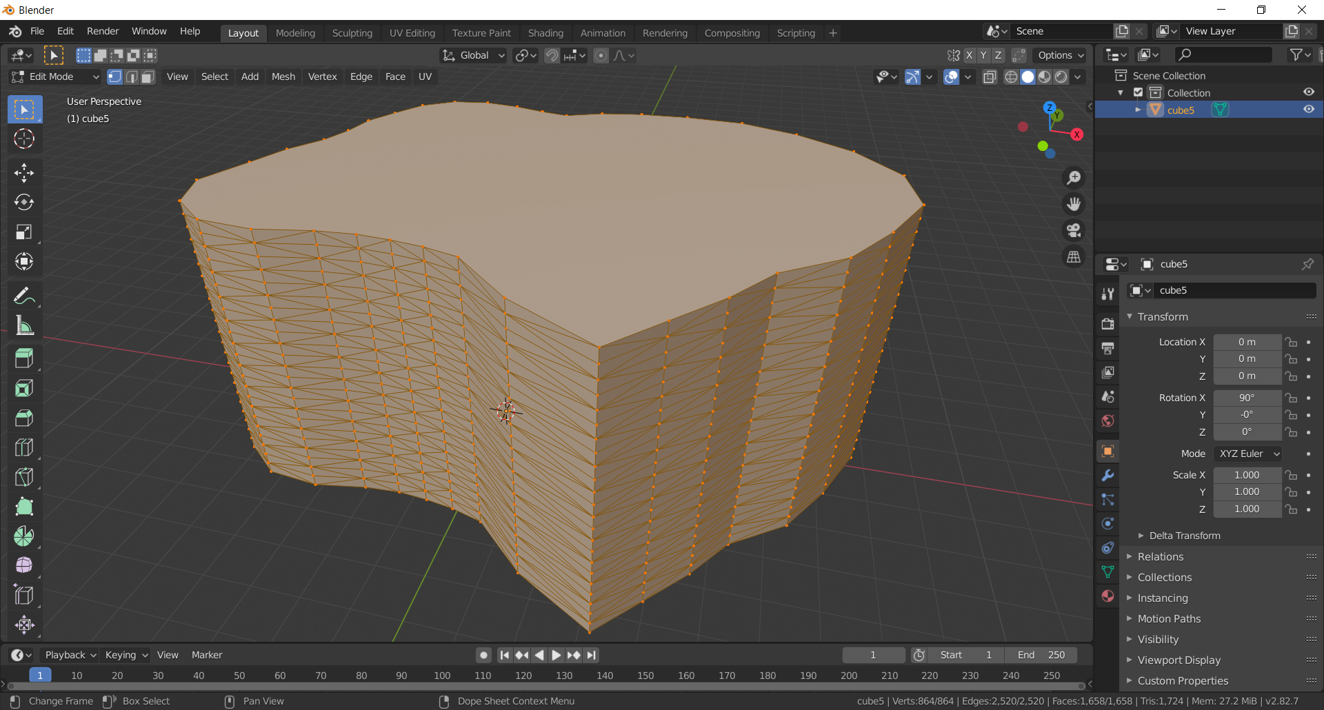
In addition to creating a flat plane, I wrote some code that turns the flat plane into a 3D object. I'll explain more in Part 3, but the basic idea is that as the object increases in height, each vertical point becomes one of the points of a triangle on the exterior surface.
This particular object wasn't scanned in - it was basically just extruded along the Z axis, so the walls of the object are uniform in their vertical dimension. Each "layer" is identical. On real objects that are scanned in, each layer would be a little different, and the triangles are good at representing those differences.
Part 1
Part 3

