DIY DYNO RUN
October 12, 2009
by: jovial_cynic
by: jovial_cynic

This last week, I decided to assemble an in-car dyno for my 510 so I can finally see what kind of horsepower I'm pulling, using an application that can process a signal coming off the negative terminal of the coil in the engine bay.
The software is an old application called Street Dyno, and from the looks of it, the last available version that can be found online is v0.6.0. I believe that v0.6.8 was the actual last free version available before it went commercial in a v1.0 version, but no trace of that program can be found on the internet at this time.
It looks like v0.6.0 is sufficient; I've been able to pull some consistent dyno runs, and I'm satisfied with the results.
In order to pull the signal from the coil (which is coming in hot at 12 volts), you have to build a simple voltage-divider circuit. Here's a diagram:

It may look a little complicated, but it's basically taking the 12 volts and splitting it, using nothing more than two resistors -- one is a 33k ohm resistor, and the other is a variable resistor (rheostat or potentiometer) that can provide up to 25k ohms of resistance. I'm using a 10k ohm potentiometer in my circuit, only because I know that the circuit is looking for a low resistance amount; I could get away with a 5k pot and still be fine.
By tuning the resistance low enough on the variable resistor, you can reduce the voltage between "V out" and "Grn out" shown on the circuit. You don't want the whole 12-volt coil signal going into a microphone line on a laptop -- you'll fry it. This voltage divider circuit allows you to bring the signal down to about 0.1v, which is low enough to keep the laptop safe, and high enough to produce a usable signal.
YOU-MIGHT-BREAK-YOUR-LAPTOP WARNING!!!
Test the voltage on the jack. Go get a volt meter and actually test the thing. If your potentiometer sets the resistance too high, you'll end up with too much voltage going through the system. I tested before plugging it in, and found that because of a break in the solder between the pot and ground, I was pushing over 12 volts through the jack, and would have been minus one laptop. TEST IT FIRST.
Here's a closeup of the circuit on a tiny circuit board:

I decided to mount my circuit inside an empty film canister:

The "V out" and "Gnd out" lines actually go to a standard headphone/microphone jack, to be plugged into the microphone line and literally recorded onto the laptop using a sound recorder. In Windows, the basic Sound Recorder software works just fine. You just have to make sure to save the .WAV file in 8bit mono format.
Once you record it and trim off the noise before and after your 2nd-gear pedal-to-the-floor run, and after you enter all the necessary variables into the Street Dyno software, you can pull the .WAV file in and have it produce a horsepower and torque curve.
Here are my first two runs. On the graph, red = HP, and green = torque. The blue/purple line is an amplified "echo" in the wires, which is picked up by the software. The software is sophisticated enough to pick out the valid signal, but it leaves the echo on the display. I may pick up some shielded wire or twist the signal and ground wires to reduce the signal echo.

107hp run
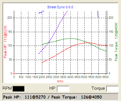
111hp run
On the first run, I let off at around 5700 rpms, but on the second run, I ran it out to 6500 rpms. Because of the difference, the two runs produced two different x-axis numbers (this is an auto-scaling feature of the software). The problem with the different x-axis numbers, however, is that it makes overlaying require a couple of extra steps. The only way to overlay the two runs is to do a screen capture into image editing software and stretch the run with the wider range to make the numbers line up.
Here are the two results, merged:
As you can see, the car is consistent. Between the 107hp and 111hp run, the torque curve is the same, which allows me to begin tuning the car to see what kind of results I'll get.
With the upper value currently at 111hp at the wheels, that's giving me an estimated 138hp at the crank. Note: the crank horsepower is the figure you hear auto manufacturers mention when advertising their cars.
Additionally, an 111hp figure gives me an estimated quarter-mile time of 15.9 seconds.
This first set of dyno runs provides me with some baseline figures. With some key variables (ignition timing, fuel ratio, etc.) that I can tune, I'll be able to see true differences on the dyno curves and bring my little project car up as close to optimal performance as I can.
My engine build:
A87 open chambered head (combustion chamber volume: 45cc)
Shadbolt cam (510 lift, 280 duration)
Z22E block, bored out .75mm over
Bore size: 87.75mm
Stroke: 86mm (L20b crank)
Piston volume: -9.32cc (stock Z22e pistons, but they are shaved down a bit, so this might be a little less)
Deck clearance: .2mm over deck (shaved down from .4mm)
CR: ~9.58:1
Breathing with dual 38mm SUs
4-to-1 Header
2.25" exhaust, "cherrybomb" muffler
Timing: Initial-20, Total-36
Fuel Mix: O2 gauge says it's in the neighborhood, and quite rich during WOT.

