Jason Gray's Turbo Install
I became intrigued with the idea of turbocharging my 510 several years ago but had no actual experience with turbo engines and a limited budget. Info for actually building a successful turbo 510 was scarce so I made many mistakes along the way. On this page, I will try to pass along some of the collective knowledge and advice I have gathered in the course of my project. One thing I have learned is that before starting, you should have a clear understanding of what your options are and what you are trying to accomplish.
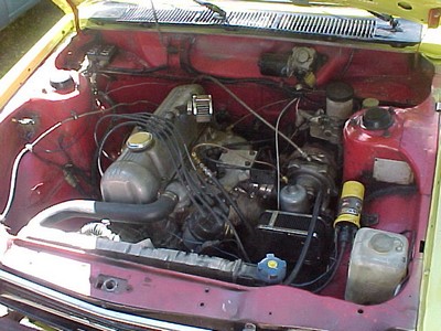
My stone-age technology turbocharged L16.
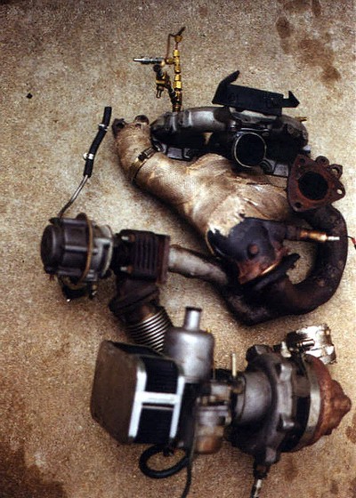
My turbo 510 project started when I got a lead on a turbocharged L16 for sale. The motor was a L16 that had been turbo'd and installed in a Lotus 23 racecar back in the early 70's in pursuit of Datsun Competition dept racing contingency money. The motor was successfully tested on a track for several hours but then the project was shelved and the motor was not used again. The story I got was that the car driver was scared to drive the lightweight racecar with this motor. The current owner of the lotus was restoring the car and had no interest in the Datsun stuff. For I got an entire turbo'd L16. This system was really primitive, used a Rajay 377b25 turbo adapted from a 1970 VW beetle turbo kit, a single bendix-zienieth carb that looks like it came from a lawnmower (motorcycle actually), stock L16 intake and exhaust manifolds and no wastegate.
The first thing I soon figured out was that there was no way the lotus setup would fit a 510 so I set about re-plumbing to fit in a 510. The stock 510 exhaust manifold is the biggest problem- the exhaust outlet is too low to plumb to a turbine and the twin outlets complicate plumbing further in an area already cramped for space. I searched around and found a later '78 HL510 L20B exhaust manifold that was a 4 into 1 log design and has the single exhaust outlet higher than the stock L16 manifold. I fabricated a connector "J" pipe made from 2" mandrel bent mild steel tubing. The "J" pipe routes the exhaust from the cast iron manifold upward to the turbo. The long connection from exhaust to turbo is less than ideal and will be prone to leaking but I saw few other options at the time. I wanted to avoid welding a new flange on the cast iron manifold because cast iron is difficult to weld without cracking. Professional cast aftermarket turbo manifold were made back in the '70s and '80s but are no longer available. Fabricating an entire new header exhaust manifold with turbo outlet flange is another option. Stainless steel would be the best material to use but mild steel would be cheaper and easier to weld. Cast hydraulic pipe fittings called "weld-els" are probably the best choice for fabricating a header type turbo manifold. An example project with pictures of a weld-el manifold is on the SDS website. (this site has a lot of great turbo info, read their tech FAQ and projects sections!).
On the suggestion of the Turbo Tom articles in 510 again and on my own further research, I had decided to retain the draw-through carburetion configuration (vs. blow-through). EFI is undoubtedly a superior way to fuel a turbo engine but I wanted to avoid the complexity and cost of EFI. I am comfortable tuning and modifying carburetors, I am clueless and terrified of EFI and didn't yet want to invest in a tunable aftermarket EFI controller.
I analyzed all of the possible placements of the turbo and settled on locating it slightly below the intake manifold, with turbine outlet facing toward the firewall and with the compressor outlet centered between #2 and #3 cylinders. Several of the old '70s era kits (like cartech) used similar placement of the turbo, though usually with a custom intake manifold that allowed placement of the turbo closer to the engine. The placement is also very similar to the original crown turbo kit for the 240Z that utilized the SU manifold. Another option is too install the turbo "backward" with the exhaust exiting toward the front of car and the compressor intake toward the firewall. Then, compressor discharge can be centered between #2 and #3 cylinders and blow into the top of the stock intake manifold, carb is located above the steering box. Many of the carbureted Turbo Tom installations utilized similar routing.
I really wanted to avoid using the plumbing routing of the original crown 510 turbo kit. In this configuration, the carb faces forward, exhaust rearward like my setup but the compressor discharge is located forward of the intake manifold and requires a 180� bend connector pipe to route the pressurized air/fuel back toward the top of the stock intake manifold. With draw-through carburetion, separation and puddleing of the air/fuel is a serious concern. All the books I read said to avoid such configurations where the air/fuel is required to take extra "bends" and enters the manifold plenum with velocity that biases mixture toward the rear cylinders.
For an intake manifold, I used a 710 L20B "stovepipe heated" manifold. This manifold has no water jacket as it was designed to be heated by exhaust manifold heat. The intake manifold has a thin steel plate covering a hole below the stock carb location that sandwiches between intake and a special exhaust manifold to heat the incoming air/fuel. (I am not using the matching stovepipe exhaust manifold.) I fabricated an inlet that angles out the bottom of the intake manifold through the stovepipe plate. (seen in above picture) The normal carb location on top of the intake manifold is blocked off. I had the manifold flange milled at an angle so manifold tips upward, away from the exhaust for adequate clearance for the new inlet. The turbo compressor blows upward to the intake manifold through a short silicon connection hose.
The benefit from my intake routing is that the intake path is very short (essentially the compressor blows directly into manifold plenum) and utilizes a stock intake manifold to provide for excellent air/fuel distribution. The only problems I have had with my manifold inlet is the close proximity of the silicon connection hose to the hot exhaust manifold. The first silicon hose I used melted due to the exhaust manifold heat. Next, I wrapped the exhaust manifold with insulation and wrapped the silicon hose with foil to protect the hose but exhaust heat undoubtedly transfers to the intake. I was also able to rework the intake manifold inlet pipe to sit further from the exhaust manifold so that even more heat shielding can be used and further "melting" of the silicon hose has not been a problem. Update: After 5000 miles of use, I unwrapped the header tape from my cast manifold to find it had cracked due to the excessive heat held in the manifold. Don't use header wrap tape with cast manifolds!
Utilizing a stock cast manifold is still probably a viable idea but I instead chose to replace it with a custom fabricated exhaust manifold to provide even better turbo placement and shorter exhaust path.

The VW turbo kit came with single sidedraft bendix-zienith motorcycle carb. The bendix-zienith carb looked really primitive so I replaced it with a slightly larger single 44mm SU (from a Volvo). The carb bolts directly to the compressor inlet with a thin adapter. I used an '85 200sx pedal and throttle cable to actuate the SU carb. I have seen examples of other SU carbureted turbo setups including a 250+hp 240Z fed by a single SU. The 44mm carb bore is sized close to the 41mm diameter of the entry of the turbo compressor (inducer) so the single carb should not present an additional restriction to the airflow. A single Weber DCOE is often used in turbo installations but this requires a fairly complex "Y" adapter to route the two carb bores into the compressor inlet. DCOE plumbing seems overly complex and the extra airflow capacity of the twin bores is really not needed given the size of the compressor inlet. Downdraft carbs are also often used but this requires a 90� adapter to plumb into the compressor and provides another opportunity for fuel puddeling.
The SU carb works well with the turbo. I have the needle jetting setup so the motor cruises lean while not under boost for fuel economy. Only when the boost comes on does the slide piston fully raise the fuel needle. A small needle tip provides ritch air/fuel mixture while on boost for detonation resistance. From the lambda sensor gauge info, the air fuel mixture remains ritch even while at full boost at high RPM. The limitation to fuel delivery for this carburetor will be the float bowl inlet valve. I have not reached the fuel flow limit of the inlet valve yet, but a larger, higher HP motor could conceivably drain the floatbowl faster than fuel can be pushed into the floatbowl through the single inlet valve.

A clearance problem existed between turbine and the 280zx master brake cylinder I was using. (280zx front brakes on this car). I substituted an '85 200sx brake master cylinder. This master is shorter and brake lines attach differently (from the side) so don't interfere with the turbine and exhaust. I mounted the master cylinder about 1" higher on the firewall (vertical bolt pattern, located on the top set of bolts that normally hold on the backing plate). The flange of this master is designed to hold the master cylinder inclined upward so the foreword tip is even higher. This built in tip-up also corrects the angle of the actuating rod with the higher mounting location. The brake master now sits with 1-1/2" clearance to the turbo and I constructed a heat shield to keep from radiating heat from turbine to master. I later found that the brake master from a Nissan KA24 pickup is similar design but the lines exit toward left side, away from hot turbo. The pickup master would have worked even better. If you need additional clearance for sidedraft carb filters or airhorns on a NA motor, the 200sx or KA24 truck master might be a good option.
Using aluminized mandrel U-bent tubing, I constructed a very smooth 2-1/2" exhaust system with nearly stock routing. A large diameter exhaust with smooth bends is key to good turbo motor performance. Any backpressure on the turbine outlet is undesirable. 2-1/2" tubing is the largest size that can be passed through a unmodified 510 rear X-member. If you care to modify the crossmember to accept even larger pipe, go for 3" pipe for even better performance.
The motor I bought with the turbo was a rusty piece of junk so I set about building a fresh L16 from my collection of parts. I have plenty of L16 spare parts I would otherwise never use so if I kill a few L16's, it is really not a problem. I have not managed to kill the first L16 yet, it survived severe detonation during my initial testing of the motor. The VW kit that I got the turbo from was originally sized for a 1600cc so I reasoned it would be best to stick with the L16. I happened to have a round port, peanut chambered w58 head with a fresh valve job donated to my project so I needed a round exhaust port head to match the exhaust manifold. (Ive since learned that similar square port 4-into-1 manifold may exist and allow use of the better flowing square port head). The wider manifold gasket surface of the round port head should be more resistant to blowing out the gasket below #2, #3 ports where the gasket is thin on a square port head. To reduce compression with the L16, I used the 37cc head with shorter L18 rods and 240Z flattop pistons (stuff I already had). A open chambered (45cc) cylinder head would have been easier way to reduce CR with a stock L16 bottom end. CR for my L16/240z/L18/L20B parts combo is 7.8:1.
After several months of trial fitting and fabrication, I got everything plumbed together and fired up the motor. It took a bit of work to re-jet the SU carburetor well enough to test run. I wound up custom making a SU fuel jetting needle with the taper dimensions needed. I made the needle from a 1/8" brass welding rod chucked into a high speed grinder like a mini-lathe. Using a bosch lambda air/fuel sensor and an Intrellitronix LED bar gauge to monitor air/fuel ratio helped to figure out how to modify the profile of the SU fuel needle.
The turbo developed excessive boost without a wastegate during initial testing. I would see up to 20psi boost on the gauge (with severe detonation) for short time before I backed off throttle. Once boost hits about 10psi things get real exciting and happen fast. Incredible rush of power but with severe detonation at higher boost levels. This was really an unusable system without boost control. So much for the "theory" of sizing the turbo to the motor and using intake and exhaust restriction to control boost (bad idea). I bought an external wastegate from a junkyard turbo Audi 5000 for and plumbed it into my turbine connector pipe. The Audi external wastegate is well made and is similar design to the aftermarket wastegates used on high output import drag race motors. External wastegates are said to do a better job of preventing boost creep than internal bypass wastegates but are more hassle to plumb into the exhaust pipe. The wastegate works great to regulate the boost. I started by running at the stock Audi boost level (7 PSI) but later modified for increased adjustable boost control.
I modified a distributor vacuum advance canister for boost controlled ignition spark timing retard. On the back of the stock L20B Electronic Ignition vacuum canister is a round shaft that pushes into dizzy to hold the canister in place (the actuating rod passes through center of this tube). Find a spring with ID slightly larger than the OD of the attaching tube. The spring I used has wire diameter of 1.5mm, 21mm coil outside diameter, 5.5mm spacing between coils. Drill a 1/8" hole in the backside of the canister next to the attaching tube and you can then thread the spring into the canister from the backside. Just start the end of the spring and wind it into the canister like threading in a screw. You then have a spring on each side of the canister opposing each other. (see picture below) The diaphragm will assume a neutral position at atmospheric pressure, advance under vacuum and retard spark under boost. I wound 3.5 coils of the spring into the backside of the canister. You also have the ability to adjust pre-load on the vacuum side spring with the adjustment screw under the putty blob. The outer adjustment screw ads pre-load, the inner screw limits travel and should be cut shorter so that full range of canister travel is available. The outer screw allows some adjustment of the amount of boost retard once the spring is inside the canister. Using a mity-vac hand pump and vacuum/pressure gauge, I set up my canister to advance 17� under 15 in-Hg vacuum and retard spark by 8� at 5 PSI boost. For each 1mm of travel of the vacuum canister actuating rod, the timing is changed by 4.24 crankshaft degrees. After the adjustment is set, re-seal the threads of the adjustment screw with hardening gasket compound. Before the boost retard modification, I had detonation problems even at 7psi. I first tried 6 degrees boost retard (36 deg-6deg= 30 degrees max advance under boost). 6 degrees was not enough to eliminate all detonation. 8 degrees retard needed to eliminate the detonation.

Above picture shows how an additional spring was screwed into the backside if the vacuum advance canister. (spring was later cut shorter for actual use).
The stock Audi 7psi boost level just wasn't enough HP for my small 1600cc motor. I built a manual boost controller to raise the boost. For wastegate controller description and fabrication diagram see my manual boost controller page. With a wastegate adjuster, I raised the boost level to 12PSI. Huge increase in HP from the 7psi I was using. At 12 PSI there is no audibly detectable detonation but I was worried about killing the motor so turned boost down to 11psi to have a small cushion of protection. It has run with max boost level limited to 11psi for 1000 miles with no evidence of detonation. I also rigged up a water injection system using a electric windshield washer fluid pump triggered by a full throttle switch. The water squirts directly into the carburetor throat and is atomized when it hits the spinning turbo. The H2O atomizing cools the compressed air and the resulting steam serves as an effective anti-detonate during combustion by slowing the flame front thus reducing occurrence of detonation. The steam also helps keeps the combustion chamber clean from carbon build-up. I used a needle valve to regulate the volume of H2O injected into the carb. Excessive H2O will result in a decrease in power output but a small amount of H2O does not noticeably effect power and greatly raises the threshold for detonation, just don't run dry of H2O! A couple of good website with H2O injection info are http://www.dawesdevices.com/water.html.
Driving the turbo car takes some adjustment as compared to my other 510 with L20B naturally aspirated motor. The power is not so instant but builds up and pulls ever stronger to full boost. The turbo L16 is noticeably more powerful than my NA L20B. The turbo motor is really in its element on a fast hiway drive. The boost is load sensitive so actually feels increasingly strong in higher gears. Cruising fast on the hiway, it can really surprise another car cruising at the same speed to suddenly see the 510 pull away with the boost on. Unlike a naturally aspirated motor that starts to run out of breath at high speed, the turbo seems to thrive on making power while at high loads. Driving the turbo car in stop and go traffic is not as fun as my L20B. It just doesn't have the immediate snap to instantly apply power like the webered L20B. With aggressive clutch slipping from a 4500RPM launch, best performance was 0-60 mph time of 8.2 seconds and 1/4 mile of 16.15 sec @ 88 MPH. This would indicate approx. 115-120HP at the wheels, 140-145 at the flywheel. Launching produces a lot of wheelspin, wider, stickier wheels would bring this time down considerably.
Update: I have taken my turbo 510 off the streets for the duration of the Alaska winter while I work on a new motor. Turbo power in a non LSD RWD car on icy roads doesn't work well. Carburetor icing on humid, cold days was also a problem. One complaint I often hear from draw-through carbed turbo setups is hard starting in cold weather. My turbo engine setup never failed to start in mornings as cold as 15�F. It actually cold started fairly easy even then. I credit this to the short and uncomplicated intake plumbing.
I am transferring the turbo setup to a larger motor. Clearance between turbo and the strut tower and brake master was originally a concern that somewhat limited me to L16/L18 block size with the original manifold/turbo setup but I gained clearance by reworking motor mounts to offset the entire motor approx. 1" toward passenger side and leaning the motor over several degrees further toward passenger side. I am using a larger L20B, stock bottom end and a open chambered cylinder head with chambers unshrouded, smoothed and enlarged to 50cc, the compression ratio will again be around 7.8:1. Tearing apart the L16 setup after 5000 miles of use, I found that part of the metal gasket I was using between manifold and connector pipe had broken and passed through the turbine wheel, damaging the wheel. Rather than rebuilding the 30 year old Rajay turbo, I am making the switch to a modern turbo better sized to the motor. The turbo I am using is a garret T3 from a 2.3L ford, -60 trim compressor and .63 a/r turbine. An integral wastegate has greatly simplified the manifold plumbing. I have found that garret T3 turbos are fairly plentiful among the 280ZX/300zx, Chrysler turbo- GLH, Daytona, LeBaron and the ford 2.3 turbo Mustang and Thunderbirds and only cost from local pick-n-pull junkyard (likely needing rebuild). Websites with a lots of good Mopar turbo are at minimopar.com (useful info for selecting and matching your turbo) . If you are planning a draw-through carb setup, beware that some junkyard turbo may be unsuitable if lacking a oil seal on the compressor shaft bearing. Manifold vacuum will suck oil into the intake when the throttle is closed if you don't have the required shaft seal. The earliest of the turbo Chrysler cars with EFI throttle body located upstream of turbo definitely did use a suitable compressor oil seal for draw-through carburetion (though Chrysler turbos utilize and unusual angled compressor discharge housing and non-standard turbine flange). If you are having a turbo rebuilt, it is possible to have an oil seal added to a compressor lacking one. The modern, smaller diameter turbo is easier to physically fit into the 510 engine bay, they can scroll up faster for reduced boost lag and make more HP at a given boost level than the antique Rajay. I have custom fabricate an entirely new mild steel header/manifold from cast hydraulic pipe fittings to avoid using the stock manifold and connection pipe. A header type exhaust manifold makes better use of the exhaust pulse energy to bring the boost on faster.
I think I have shown myself that it is possible to homebrew a simple turbo setup for a 510 for minimal cost. It has definitely been a great learning experience and I can take pride in designing and executing my own custom installation. The only real skill I had to learn was the welding (and that has been the fun part!).
Suggested Turbo References
5 part TURBO TOM series in back issues of 510 AGAIN. (from the early 90's). Tom's articles are the most 510 specific turbo references I have found. Tom has probably built more turbo'ed 510s than anyone else around and he has done several decades of actual testing. His articles provide lots of practical information that can save you lots of effort. He really stresses importance of a low restriction exhaust system and good fuel delivery to carb. For carburetion, Tom is much in favor of draw through setup, detest blow through. Try ordering the relevant backissues from 510 again.
TURBOCHARGERS, by Hugh McInnes, HP press 1984. Good introductory explanation of turbocharger theory and system design and installation. Material somewhat dated but still very useful, especially for the DIY turbo installation.
MAXIMUM BOOST, by Corky Bell. More up-to-date information than McInnes book, Much more EFI info. Perhaps does not have as much shadetree do-it-yourself info as McInnes book but is modernized and more targeted for people that want a pre-fab turbo kit installed on a modern car. Corky favors blow-through carbs in favor of draw through. (And greatly favors EFI over either). Good section covering construction of custom exhaust manifolds from weld-el fittings. Look for this book on shelf of Barnes and Nobel bookstore or order online at http://www.cartech.net/maximumboost.htm