GAUGE CONTROL MODULE
May 13, 2021
by: jovial_cynic
by: jovial_cynic
I started this project because I wanted to see if I could drive a few gauges I owned using the AtTiny85 microcontroller and the sensors that came with my car. In particular, I wanted to display the values for the following:
- Fuel Level
- Oil Pressure
- Coolant Temp
- Fuel Pressure
Because my Datsun 510 is entirely custom, it means that I don't have any of the original gauges. Even if I did, I don't have the original engine, so the sensors wouldn't play nicely with the factory gauges anyway. A custom solution seemed to make sense.
The first step was to get the resistor value ranges for the sensors. Most sensors have some kind of increasing or decreasing amount of resistance, depending on what is being measured. My fuel tank has a float that raises an arm, and as the fuel level decreases, the sensor resistance increases.
In this specific example, the fuel level sensor has a range of 10ohms (full) to 80ohms (empty). From everything I've read about the stock Datsun 510 fuel level sensor, it's a fairly linear relationship. That would mean that 38ohms is roughly half-full.
The next step in this project is to create a voltage-divider circuit.
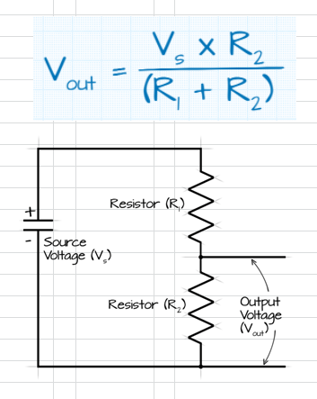
Basically, this allows you to read a voltage output that will vary, depending on the change in resistance of either one or both of the resistors. If I use a fixed 100ohm resistor in the circuit and push 5v through it, the circuit will generate an output that can vary between 0v and 5v, and that will give me the analog voltage data I need to drive my gauges.
Just for kicks, here is the data and graph that I set up in Excel for the fuel level sensor voltage divider circuit.
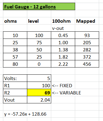
This shows the ohms, the fuel level (in percentage) in the gas tank, the voltage output from the voltage divider circuit, and the 10bit value that the AtTiny85 will see when it reads the 0-5v signal. Below that is my little voltage divider circuit calculator that I used so I could see what the voltage would be, given any ohm reading between 10 and 80.
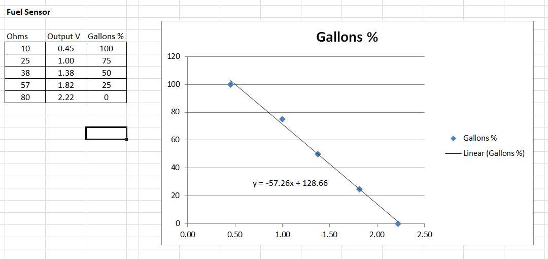
This graph has the same basic data, but shows it in graph format. Excel has a built-in feature that lets you see the slope (or polynomial) formula (y = -57.26x + 128.66) based on the plots on the graph, which will prove to be VERY useful later.
You'll notice that I'm using percent-full for my data. I could have used actual gallons, but because fuel gauges are really about showing that you need to go to a gas station, it doesn't actually matter how many gallons the tank can hold. That's not terribly useful data for my purposes, so I went with percent-full instead.
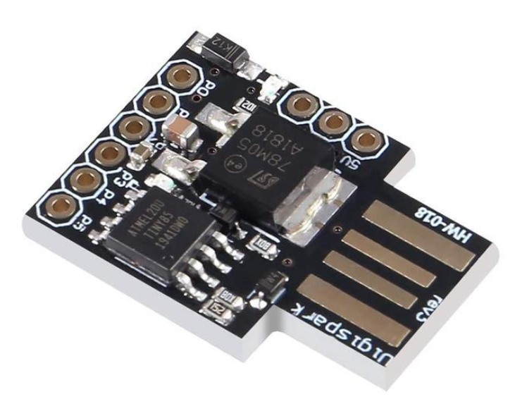
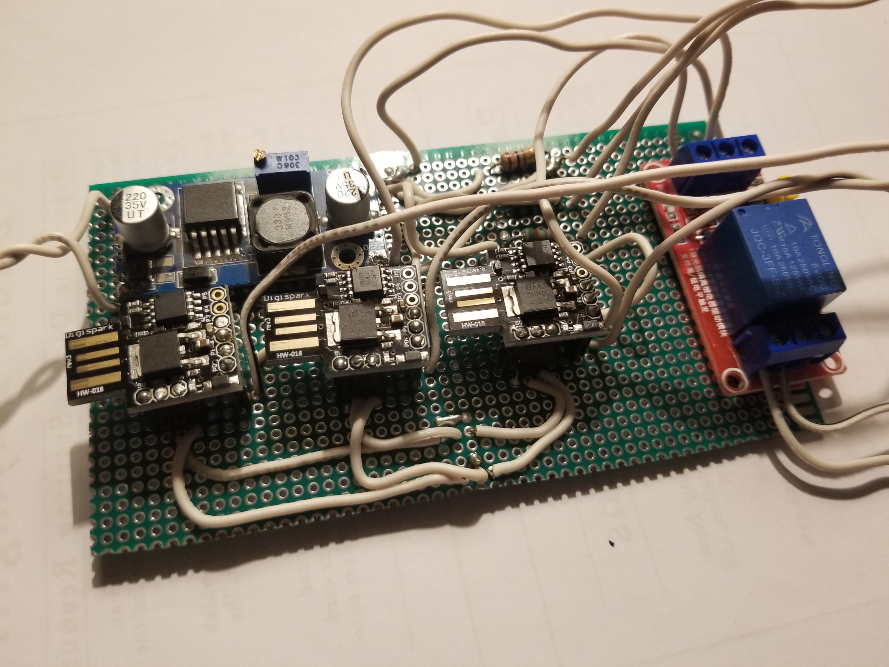
So, armed with all the data I need, I moved onto the programming the AtTiny85 to do my work. Well, three AtTiny85s. I have three of them for this project, and they're powered by a buck-converter that's taking the 12v car power and bringing it down to 5v for the AtTiny85s and the gauges. If you don't know, the AtTiny85 is like a smaller, less-powerful Arduino. You can use the same basic code, although there are some hardware specific features that aren't available. But for this project, it's perfect.
On the AtTiny85, I'm using the analog input pin (A0) to read the voltage coming in from the voltage divider circuit and running that data through the following processes:
1. Read the voltage into pin A0. That data comes in a 10-bit format, so to convert the value into something that makes sense, you divide 205 by the voltage reading, and that gives you the actual voltage.
float sensorValue = analogRead(A0);
sensorValue = sensorValue / 205;
So, here's an example: Let's say that the resistance from the fuel tank reads 38ohms. If you run that through the 100ohm voltage divider circuit and push a 5v source through it, you end up with a 1.38v output. That shows up as 283 on the analog-to-digital converter, so divide that by 205, and that gives you 1.38v.
As a side note, I'm only doing the "divide by 205" to make my code easier for me to follow. I want the next formula to be a "voltage -> percent-full" value, so I did this for convenience. It's probably cleaner to keep the original ATC value and do the math that way, but I wanted to do it this way.
The next step is to run the voltage through the slope formula from before: y = -57.26x + 128.66
This part of the code looks like this:
percentFull = (-57.26 * voltage) + 128.66;
So, if you put the 1.38 volts into the formula, you get:
(-57.26 * 1.38) + 128.66 = 49.64
Well, 49.64 is basically 50. And because my formula is designed to output a value between 1 and 100, we're showing a tank that's half-full. Or half-empty.
The next thing to do is to take the "50" value and make that output to a gauge somehow. The AtTiny85 has a pulse-width modulator (PWM) output based on a 0 (no output) to 255 (constant output). As it turns out, 5v panel gauges treat PWM output a bit like regular voltage; PWM 255 = 5v on the gauge, and PWM 127 is about 2.5v on the gauge. Since I'm trying to make a value of 0-100 and output it to a value between 0-255, I use the map function:
pwmOutput = map(percentFull, 0, 100, 0, 255);
And then I send that mapped value to the gauge:
analogWrite(A0, pwmOutput);
That's really all there is to the fuel level sensor and gauge output.
The oil pressure is essentially identical, only the ohms range from 10 to 50, and rather than percent-full (which makes no sense on an oil pressure gauge), I'm outputting the actual pressure values (0 to 80PSI), with the target PSI being at 40. The voltage divider circuit is different due to the different resistors needed to make it work properly, and the slope formula is also different. Lastly, the map function will read 0 to 80, so that the target value of 40 ends up in the center of the gauge. That's an intuitive way to read the oil pressure, and I wish more gauges functioned that way.
The water-temp has some of the same differences, but I'm adding one additional function to AtTiny85: once the water temp hits 200F, the microcontroller will send an "on" signal to a 5v relay module, which will flip a switch to turn on the 12v engine fan. This will prevent me from having to keep the fan running all the time.
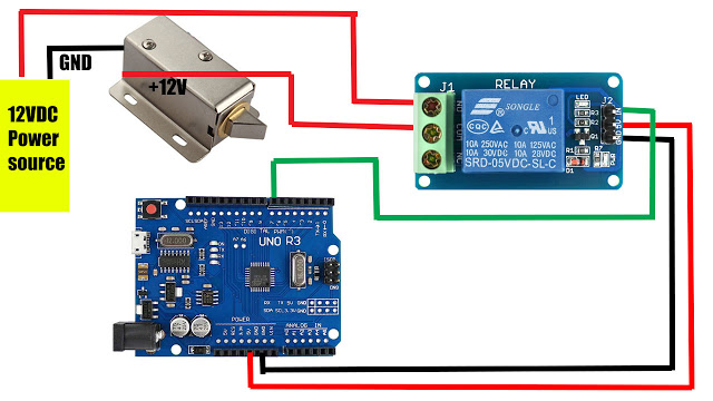
This is an image of the relay module hooked up to a traditional Arduino, but it works with the AtTiny85 the same way.

